
العربية
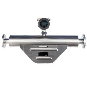
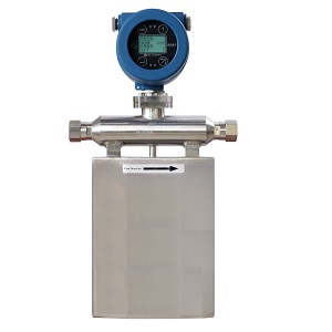
قياس مباشر لتدفق الكتلة. ±0.1% إلى ±0.2% للسوائل ±0.5% للغازات قياس الكثافة، ودرجة الحرارة، والضغط نسبة نطاق واسعة تصل إلى 100:1
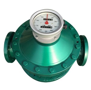
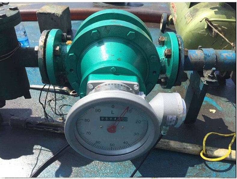
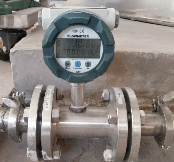
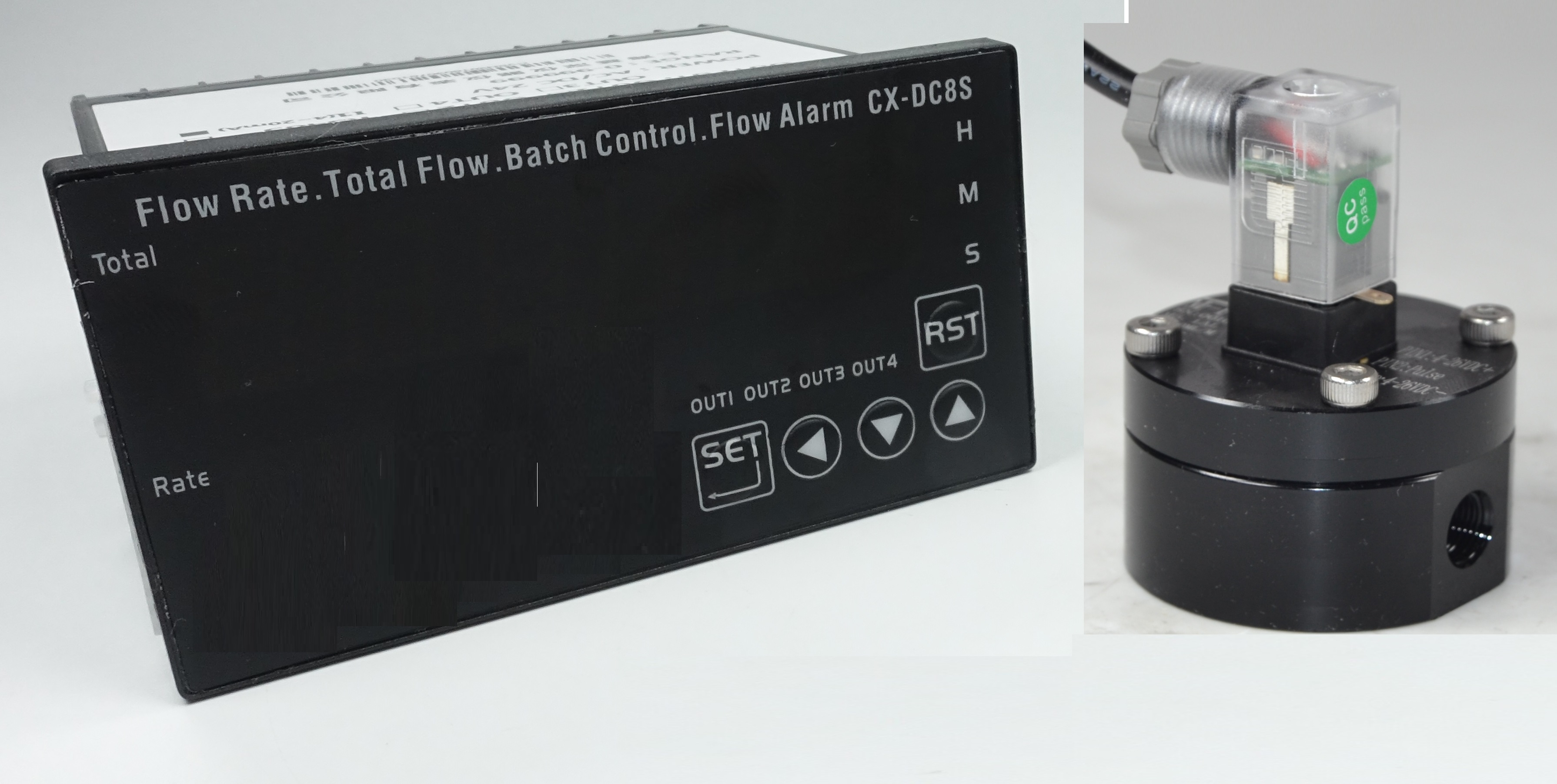
لماذا يمكن استخدام عدادات التدفق الإيجابي للوقود والزيوت؟ الوقود أو الزيوت قياس التدفق الحجمي يشير إلى الديزل ، والوقود البترولي ، والكيروسين ، وزيت التدفئة المنزلية ، ووقود الطائرات ، ووقود الديزل ...
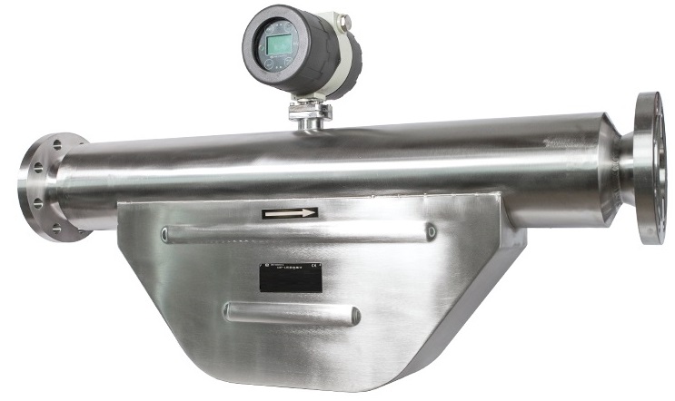
مقياس تدفق كتلة زيت الوقود هو نوع من مقاييس التدفق المصممة خصيصًا لقياس معدل تدفق كتلة زيت الوقود في خط أنابيب أو نظام معالجة. ويُستخدم بشكل شائع في التطبيقات الصناعية مثل توليد الطاقة والنقل البحري وإنتاج النفط والغاز.
قياس تدفق زيت الوقود، بما في ذلك زيت الوقود المقطر، والنفط الخام، ومقياس تدفق زيت الوقود المتبقي، والوقود الحيوي، ومستشعر تدفق كتلة زيت وقود السفن، وجهاز قياس تدفق زيت الوقود الثقيل، وحرق الوقود الأحفوري، والديزل الحيوي، والوقود البحري. عدادات تدفق الوقود متجدد ديزل تُستخدم أنواع الوقود الاصطناعي والنفط في محركات الديزل، والغلايات والأفران الصناعية، ومحطات توليد الطاقة، والسفن البحرية.
لست متأكدًا من مقياس التدفق المناسب لزيت الوقود الخاص بك؟ تحقق من قسمنا دليل شامل لعدادات تدفق زيت الوقود يشمل ذلك الديزل والبنزين والكيروسين.
مقياس تدفق كوريوليسيُعد خيارًا مثاليًا لـ قياس تدفق زيت الوقود يتكون مقياس تدفق الكتلة كوريوليس عادةً من أنبوب تدفق ومستشعرين لقياس قوى كوريوليس الناتجة عن السائل أثناء تدفقه عبر الأنبوب. تتناسب قوى كوريوليس طرديًا مع معدل تدفق كتلة زيت الوقود، مما يسمح بإجراء قياسات دقيقة وموثوقة للغاية.
تتميز عدادات تدفق كتلة زيت الوقود بقدرتها على قياس نطاق واسع من معدلات التدفق، من المنخفضة جدًا إلى العالية جدًا، كما أنها مناسبة لمختلف أنواع ولزوجات زيت الوقود. لدينا العديد من أحجام حساسات تدفق الكتلة للاختيار من بينها، بنطاق تدفق يتراوح من 1 غرام/ساعة إلى 1000 طن/ساعة. مستشعر تدفق صغير الأحجام من 1 مم إلى مقياس تدفق الزيت الكبير مثل عدادات تدفق الزيت مقاس 10 بوصات، وهي مصممة أيضاً لتحمل الظروف القاسية الموجودة عادةً في البيئات الصناعية، مثل مستشعر تدفق كتلة الزيت عالي الحرارة مقياس تدفق الكتلة عالي الضغط، ومقياس تدفق الكتلة الكيميائية للسوائل المسببة للتآكل، وقياس زيت الوقود عالي الضغط. قياس زيت الوقود عالي اللزوجة .
يُعدّ استخدام عدادات تدفق كتلة زيت الوقود أمرًا بالغ الأهمية لضمان التشغيل الفعال والآمن للعمليات الصناعية التي تعتمد على القياس الدقيق لمعدلات تدفق زيت الوقود. فمن خلال توفير قياسات دقيقة وفورية لمعدلات تدفق كتلة زيت الوقود، تُسهم هذه العدادات في تحسين أداء العمليات الصناعية أو لأغراض نقل الملكية، والحدّ من الهدر واستهلاك الطاقة، وتقليل مخاطر الحوادث أو أعطال المعدات.
 |  |
 |  |
 |  |
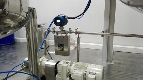
1. تعمل عدادات تدفق الكتلة كوريوليس وفقًا لمبدأ الاهتزاز. لذا، يُفضّل تجنب وجود أي اهتزاز في موقع التركيب. كما أن الدعم القوي لأنابيب تركيب عدادات تدفق الكتلة كوريوليس أمر بالغ الأهمية. في حال تعذر تجاهل الاهتزاز، يُنصح باستخدام وصلات أنابيب مرنة. ويجب أن تكون أنابيب التوصيل وعدادات تدفق الكتلة على نفس المحور. يُرجى عدم إضافة أي قوة إضافية على عدادات تدفق الكتلة، وإلا فقد تتأثر دقتها.
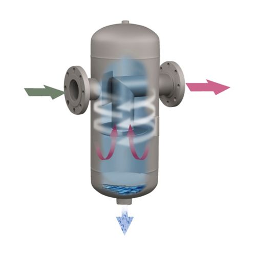
2. إذا كانت نسبة الغاز في وقود الزيت المقاس عالية، فمن الضروري تركيب خزان فصل الغاز عن السائل على مدخل عدادات تدفق الكتلة كوريوليس.
3. The throttle devices, for example the flow control valves should be installed on the outlet of the mass flow meters.
4. The mass flow meters should be installed away from the outlet of the pumps. Especially for the Dual pumps, if the installation distance is too close, then the measured flow rate could be affected, which is fluctuated.
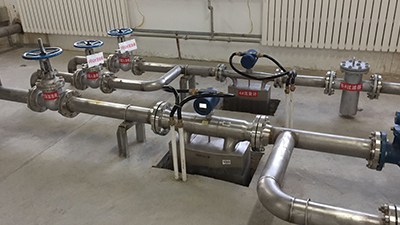
5. If measuring high temperature oil or it is required to keep warm of the measured oil, Please keep distance between the inner tubes of the heating jackets or the heating tubes with the housings of the sensor. We factory also provide the heating jackets along with the mass flow meters, for example the heating jackets for steam or transfer oil. Please specify that you need heating jacket for flow meters to silverinstruments.com
6. The measured oil should be on the suitable flowing status. If under the local environment the flowing status of the liquids is not suitable, then it is suggested to improve with other methods, for example to modify the temperature of the liquids ( increasing / decreasing the temperature of the fuel oil to make sure the measured liquids are in the proper flowing status.
7. Installation direction: please make sure the flowing direction of fuel oil should be the same with the direction marks on the nameplates of the coriolis mass flow meters. Otherwise the accuracy of the mass flow meters could be affected.
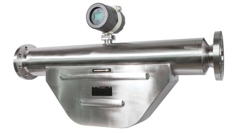
8. Please make sure the series numbers of the mass flow transmitters and the fuel oil flow sensors are one -to-one corresponded to each other. It cannot be easily changed. Otherwise the accuracy of the mass flow meters could be affected.
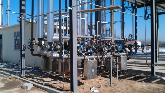
٩. إذا تم تركيب عدادات تدفق كتلة زيت الوقود في الهواء الطلق، فمن الأفضل تركيب أغطية واقية من المطر لها. ويرجى التأكد من إحكام إغلاق الغطاءين الأمامي والخلفي للعدادات. كما يرجى التأكد من إحكام إغلاق الوصلة الكهربائية لمنع تسرب المياه إلى داخل أجهزة الإرسال.
١٠. يُنصح باستخدام معدل تدفق تشغيلي عادي أعلى من ثلث نطاق التدفق القياسي لعدادات التدفق الكتلي. كما يُنصح بأن يكون الحد الأدنى الفعلي لمعدل التدفق أعلى من عُشر نطاق التدفق القياسي لعدادات التدفق الكتلي. في حال وجود أي حالة خاصة، يُرجى التواصل مع silverinstruments.com، حيث نمتلك فريقًا متخصصًا في البحث والتطوير، يُمكننا تخصيص عدادات التدفق الكتلي وفقًا لمتطلباتكم الخاصة، لضمان تلبية احتياجات المستخدمين ضمن نطاق الاستخدام المطلوب.
The integration of the Coriolis Mass Flow Meter has been connected and installed before the delivery.
The separated transmitter and the sensor are connected by the special connection cables and connectors. If the separation installation of the transmitter and the sensor is required, please contact us in advance before placing the order. The maximum length should not exceed 300m.
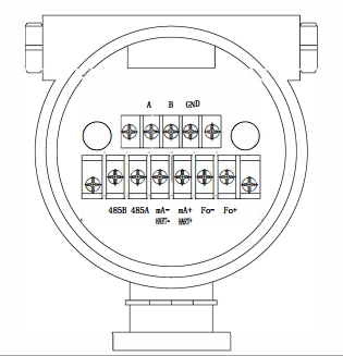
24V + \– 24VDC Power Supply (Current should not less than 500mA)
Fo + \– Frequency Output (instantaneous mass flow or volume flow)
mA + \– Current Output (instantaneous flow or density optional)
(HART + \–) HART
485A \485B RS-485 Communication (Baud Rate: “9600”, Address: “1”)
The zero point calibration is required after the Coriolis Mass Flow Meter installation. Please fill in large amount of measured medium for 10 minutes before the zero point calibration.
The zero point calibration is used to provide the benchmark of the flow measurement. The zero point must be processed after the first-time calibration or re-installation. Please make sure firstly it is required to turn off the stop valve at the exit of the mass flow meter, and then turn off the stop valve at the entrance. And make sure the liquid fulfilled the sensor is comparatively at the stationary state during the calibration. The detailed operation methods are as below video shows:
استكشاف أعطال مقياس تدفق كوريوليس
Symptom | Failure Reason | Solution |
No display | Check whether is 24VDC power supply is normal | Make sure 24VDC is working normally |
Fluctuation of flow rate measured is large | Whether there’s strong vibration of the line connected to the sensor | Adding support or switching to hose connection |
Could not enter the measuring interface after the boot | Do not connect with the sensor | Check the cables, and make sure they are connected to the sensor properly |
Zero Point Drift is large | The installation of the sensor has stress | The connecting line and the sensor interfaces should be at the same axis |
Attention: (0-10)KHz and (4-20)mA output signal is already with the power supply. It is forbidden to connect with other external power sources. Otherwise the damage of the mass flow meter could be caused.
سنتصل بك خلال 24 ساعة..